Overview
The main focus of the McRobot framework is to harmonise machine software development. Before we started with McRobot in the early 2007, every customer who decided to work with Indel controlling systems started from scratch to implement its machine functionality. The avoid such redundant coding, Indel decided to create a framework which solves all the things that have to be handled in every machine, like
- switching a machine on and off
- homing of a machine
- emergency stop handling
- correct behaviour on safety level changes
- message and error handling
An other main focus of McRobot is to have a unified interface to a machine and its modules. To reach this target, McRobot forces a one to one behaviour between mechatronic and software modules. Every module has a well defined interface, consisting of
and is written C++.
To simplify development and to allow non C++ developers or e.g. mechanical enigineers to write application sequences, Indel decided to base on the scripting language Lua for these kind of things.
Summary
Machine module functionality is written in C++ with a well defined interface. All machine sequencies are written in Lua using the methods of the modules.
Machine
The McRobot machine is the parent of all child module instances. It is responsible for the main state handling, has an own message handler and usually provides a Lua interpreter instance for the application sequence scripts.
To create an own machine instance, just implement a class derived from CINOSMcModule.
Example of a simplest McRobot machine :
mymachine.h
mymachine.cpp
To create an instance of the above object at startup, one just needs to create a machine.dt2 file in the config folder that looks like this :
Enusre that the Type value is equal to the one used in INOS_CONTAINER_CLASS, in our example MyMachine. For a detailed description of all the possible creation parameters, please refere to Parameters of class CINOSMcModule.
States
A machine has the following predefined states
- 0 startup : the machine is in startup phase
- 1 off : this is the inital state at startup an is also reached by the command Off or e.g. after an emergency stop
- 2 wait : an On command is waiting for power
- 3 on : it is under power but not yet initialized
- 4 ready : it is under power and sucessfully initialized
- 5 busy : a command is currently running
- 6 error : it does not accept any commands except the command Off until the Recover is called or a corresponding error message is confirmed
The main commands On, Off, Init are used to switch between the main states. Calling one of these commands, starts the corresponding Lua function which has to be named Mc.Hook.xxx, please refere to Hook for a detailed explanaition.
Scripting
Please refer to McLua for more information about the integration of the Lua interpreter into the McRobot framework.
Module
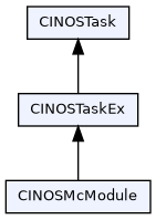
Writing an own McRobot module is really simple. If your module has axes resources, your class needs to derive from CINOSMcRobot, if it has no axes at all, derive from CINOSMcModule.
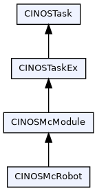
As one can see on the class diagram, a class derived from CINOSMcModule or CINOSMcRobot has its own task. This is an other central part of the McRobot philosophy. It bases on the so called active objects approach. Every module has one task and every method of the module is executed in the context of its own task. This has the big advantage that one doesn't have to care about concurrency issues and possible race conditions. Indel suggests to have one header and cpp file per module.
Creation
The following things need to be done to create an own module :
- declare an own class deriving from CINOSMcModule or CINOSMcRobot
- in your implementation register your class in the system with the macro INOS_CONTAINER_CLASS where you have to give your class a unique type name, this name is needed to create a corresponding instance
- create a Lua script named 'machine_xxx' which calls Mc.Cmd.CreateSubModule to create an instance of your module
Example of a simplest McRobot module :
mymodule.h
mymodule.cpp
The above example implements the simplest possible customer module. It provides a method called DoSomeThing and a property MyProperty. One can create an instance of this module by either calling Machine.Cmd.CreateSubModule(...) or with the following Lua script present in the projects config folder
Lua script to create the module at startup :
machine_01_mymodule.lua
The name of the lua script has to start with machine_ (be aware of the underscore) to tell the system to run this script at startup.
The first parameter of CreateSubModule defines the user specific name. The module represents itself with this name in the INCO tree, in our example the module is found in the tree under Machine.Module.Cool. To tell the system what kind of module it should create, the second parameter MyModule is important. It has to match the string used in the INOS_CONTAINER_CLASS macro. The third parameter gives the user the possibility to provide any system or user specifc parameters to the modules constructor. A possible parameter string may look like this
A detailed list of all supported parameters sorted by class
Parameters of class CINOSTaskEx
Flags
- MnW Caller task does not wait when the message input queue of this task is full. Message will be dropped
- Msg Module has a message handler (interaction with HMI)
- MsgHistory If provided, a CallProcedure named MsgHistoryTrace will be added to the Cmd folder. Executing this function will trace all messages currently stored in the “message history”. This is useful to “recreate” all traces required e.g. by McLog to check what the most recent commands were doing.
- NvR Module supports NvRam (non volatile ram)
- Stat Module supports statistics (in Stat folder)
- BaN For GetProp/GetActual: Return boolean values as numbers (for backwards compatibility with existing Lua scripts)
- CaS Enable 'async result support' check (Check async Support). If set the system checks whether async result handling is supported over the current INCO communication device (e.g. Ethernet, Dpr, ..)
Miscellaneous
- Core= Id of core the modules task should run on (default is 0), e.g. Core=2
- Prio= Task priority, default value is 31 (lowest), see also Priority
- Qsz= Modules command queue size (default is 32), e.g. Qsz=256
- StackSize= Task stack size in bytes, e.g. StackSize=32768
- Alias= Provide alias name for this task, e.g. Alias=MyOtherName (currently only used together with messages)
- TgtMsg= Definition, where to show up system/machine messages, possible values are TgtMsg=Client target messages are also presented in the mcrobot message handler, TgtMsg=Server mcrobot messages are also presented in the target message handler, TgtMsg=ClientServer both
Parameters of class CINOSMcModule
Flags
- ClJ Clear 'Prop.Job' after successful execution
- CoA Cancel on assert. Setting this flags emits a Cancel to the module in case of any task assertion.
- CoT Cancel on trap. Setting this flags emits a Cancel to the module in case of any task trap. This option is useful toghether with the fieldbus OptionEx 0x0400 (do not stop on trap) to get a more predictable behaviour in case of a trap.
- Cron Cron support: Execute a script or run a job at specified times
- Data Add data container support. Adds module commands CreateData, DestroyData and MoveData and is usually only used on machine level
- Emg Add emergency stop support, this flag is usually used on the machine level and needs a MAC.Res.Inp.Emergency="MyEmgInput" definition in the creation lua script, to tell the system what digital input it should check for the emergency stop detection (active low).
- FnM Force no message, commands are only allowed if currently no message pending
- Grd Enable guardian support: The guardian supervises the systems sensor values and starts configurable actions if certain values are reached
- Job Enable job support
- Mode Enable single step and auto mode
- Module Whether this McModule shall provide CallProcedures to create sub modules. IOW: Only McModule instances with that flag set can have sub-modules.
- Msg Module has a message handler (interaction with HMI)
- Rdy Automatically change into 'ready' state ('on' and 'init'). If set, then the module automatically sets its flags to 'on' and 'init' right during module startup.
- Script Add script container support. Adds module commands CreateScript and DestroyScript and is usually only used on machine level.
- Slc Slowmotion change. Setting this option live adjusts running moves to the newly set slowmotion factor.
- SrH Enable secure hook option, setting this option tells the system to setup the module helper hook CINOSMcModule::iModuleHlpHook only after all resources are set up successfully. This avoids traps at startup due to working with uninitialized pointers
- UnR Module supports 'unique' resources. Resources are registered in the corresponding folder (Inp,Out,Adc,Dac)
- UnLT Unique Lua Tasks. If set, attempting to start a new Lua Task with the same name as an already existing task will return an error. This is useful in situations where a script has to be executed only by a predefined number of (named) tasks, as the option avoids creating arbitrary concurrent Lua tasks with a “sequence number” as suffix in the form “taskname_[i]_”.
- CoreLua= Id of core the module's Lua interpreter should run on, e.g. CoreLua=1, if not provided, the Lua interpreter runs on the same core as the module itself
- Safety Safety supervision support (currently only for GIN-SAC4 FS)
- Optional Module is optional. CreateSubModule does not return an error if module type does not exist.
With the Cmd= parameter one can activate optional commands. Multiple commands are separated by a comma
Commands
- Cmd=GetIO Method to read the state of one or multiple IO resources
- Cmd=SetOut Method to write a digital or analog output resource
- Cmd=WaitAdc Method to wait for an analog input resoruce value
- Cmd=WaitAxis Method to wait for a axis position
- Cmd=WaitBit Method to wait for a digital input or output
- Cmd=WaitInp Method to wait for a digital input
- Cmd=WaitPos Method to wait for a position channel value
Miscellaneous
- Adc= Module has analog input resources with the given names. Names are comma-separated
- Cnt= Activate cycle counter support (deprecated)
- Dac= Module has analog output resources with the given names. Names are comma-separated
- EmgDelay= Delay until an emergency off is initiated [ms], e.g. EmgDelay=500
- EmgFilter= Filter length of emergency stop input to prevent spikes detection
- Flg= Module has flag resources with the given names. Names are comma-separated
- Inp= Module has digital input resources with the given names. Names are comma-separated
- LdnCheck= Link down check. This feature calls the iLinkDown function when the field bus state is different from “running”. iLinkDown causes: 'init flag' to be cleared (to force a re-init of the axes), calls Off and posts an error message. Usage: LdnCheck=0 to check bus number 0 or LdnCheck=0,2 to check busses 0 and 2.
- Lua=All Activate a Lua interpreter and at startup run all Lua scripts whose name case-insensitively starts with the module name, in alphabetical order except that one named modulename_lua always comes first
- Lua=script2_lua,script1_lua Activate a Lua interpreter and at startup run the named scripts (comma-separated), in reverse order
- Lua=regex Activate a Lua interpreter and at startup run all Lua scripts, whose names match the given regular expression, in alphabetical order (e.g. regex = (cool_).*(_lua) -> all scripts named 'cool_xxx.lua')
- Out= Module has digital output resources with the given names. Names are comma-separated
- Pos= Module has position channel resources with the given names. Names are comma-separated
- SimLevel= Defines the modules startup simulation level. Valid values are SimLevel=0 for no simulation, SimLevel=1 for simulation only if hardware not available, SimLevel=2 for always simulate
Parameters of class CINOSMcRobot
Flags
- CcO Concurrent On. Setting this flag forces all module axes to be switched on fully concurrent instead of sequentially
- EyI Early init. Setting this option initiates an Init command right after construction of the module. This is e.g. helpful if a module contains axes with absolute encoders. The Init command then reads the encoder values and sets the axes positions accordingly. the newly set slowmotion factor.
- IgnBc Ignore bus number check. Setting this option tells the system to ignore the fact, that not all axes of the module are conntected to the same fieldbus
- IgnTc Ignore cycletime check. Setting this option tells the system to ignore the fact, that not all axes of the module are running with the same cycletime
- IgnNc Ignore cycle number check. Setting this option tells the system to ignore the fact, that not all axes of the module are running within the same cycle number
- IgnCore Ignore core id check. Setting this option tells the system to ignore the fact, that an axis is not running on the same core like the module
- Joy Activate joystick support
- JoyDAS JoyDis async stop: For historical reasons, there exists an 'old style' and a 'new style' way of stopping a moving axis in the JoyDis (joystick disable) command: 'old style' did stopping synchronously, and therefore blocked the whole task. 'new style' performs axis stopping asynchronously and thus the task can execute other commands while the axis is being stopped. To not break existing projects, the 'new style' stopping mode must explicitly be enabled this option. For new projects, it's recommended to enable this option.
- LimitInv Use inverted limit switch handling
- SlO DO NOT USE THIS OPTION, unless an Indel developer told you to do so. Sleepless axis 'On'. This option avoid two calls to 'Sleep' during axis 'On' function, which safes 20ms for each 'On' call. This option is only suitable under very special circumstances.
- Wheel Wheel support. Setting this option allows an axis in manual mode to be handled with a hand wheel
- MPH Move Path: Enable hook for passive trajecory handling. This allows submodule to override CINOSMcRobot::iMovePathCheck or CINOSMcRobot::iMovePathHook to trigger actions along a move path.
Axis related flags They can be used e.g. in the following manner : Axs=X(WpO),Y(WpO;CpO), multiple options are therefore separated by a semicolon
- CpO Check axis position during 'On'. If set, the 'On' function for an axis will abort if the axis has already been initialized before (and thus its absolute position is known) and its currently out of the axis 'min' and 'max' range.
- FaC Force auto commutation. Setting this option forces an autocommutation on axis activation if the axis was never synced before. This can be useful if one resets the fieldbus master and want to be sure that the corresponding axis does an autocommutation sequence at the first activation. Example string for an X axis with options 'Wait for power' and 'force autocommutation' set : X=(FaC;WpO).
- IhE Inherit emergency input from McRobot. Setting this option tells the system to configure the axis enable input to be equal to the emergency input of either the module itself or its parent. This option is useful if the external axis controller does not have an 'external enable' hardware input.
- OaI On at init: Transiently call 'On' on a axis during axis init
- PlS Pure limit switches. Setting this option, e.g. AXS=Z(PlS),T enables limitswitch supervision even if the axis was not yet initted.
- Shd Shared axis. Setting this option (e.g. Axs=Z(Shd) ) marks the axis as shared with an other module.
- Slv Always slave. It can be used to force a coupled axis to be always slave. This avoids a possible wrong master/slave behaviour in case of a 'Recover' where the activation of the master axis failed for some reason, but the slave succeeded. In this case the slave axis became master, which could end up in small position inconsistencies.
- WpO Wait for power at on
- LrT Legacy reference tolerance support. Setting this option activates the before INOS r9380 used legacy reference tolerance calculation algorithm : searchstart = referencepos - referencetol*(feedperturn/gear)*0.01, searchrange = 2*referencetol*(feedperturn/gear)*0.01. Without this option the gear is only taken into account if the inc position is configured to be 'before gear' (IncPosition=0 in motor.dt2)
With the Cmd= parameter one can activate optional commands. Multiple commands are separated by a comma
Commands
- Cmd=MoveAbs Move axis to absolute position
- Cmd=MoveCarefully Move axis with reduced current and separate position error
- Cmd=MoveRel Move axis to a relative position
- Cmd=MoveToDigitalSensor Move axis to a digital sensor
- Cmd=MoveToAnalogSensor Move axis to an analog sensor
- Cmd=Border Methods for moving around borders: MoveToBorder, MoveToBorderApp, MoveFromBorder, MoveFromBorderDep
- Cmd=SpeedSet Methods for speedset handling: CreateAxisSpeedSet, DestroyAxisSpeedSet, SetAxisSpeedSet, GetAxisSpeedSet
Miscellaneous
- Axs= Module supports axes name1,name2, ... , e.g. Axs=X(WpO),Y(WpO;CpO)
States
A module has the same states as its parent machine.
- 0 startup : the module is in startup phase
- 1 off : this is the inital state at startup an is also reached by the command Off or e.g. after an emergency stop
- 2 wait : an On command is waiting for power
- 3 on : it is under power but not yet initialized
- 4 ready : it is under power and sucessfully initialized
- 5 busy : a command is currently running
- 6 error : it does not accept any commands except the command Off until the Recover is called
The commands On, Off, Init are used to switch between the states. Usually these commands are called by the corresponding parent machine script, e.g. the Mc.Hook.On() function calls the On methods of all modules.
Commands
One part of a machine or modules interface is its commands. Besides the base class commands of CINOSMcModule and CINOSMcRobot, a customer module should provide useful commands allowing to fully handle the module with all its functionality. Due to the active object approach, a command has always an external and an internal implementation. The external part runs in the context of the caller and just creates a corresponding message which is then placed into the command queue of the module. The modules task is usually always waiting for new commands on its queue. After a command arrived, the modules virtual method DispatchCmd is called, where a switch case part directs to the correct internal representation of the command. The following things need to be done to implement an own command :
- declare a public version of the command in your modules header
- declare a protected internal version of the command, Indel suggests to prepend an 'i' to the command name
- add a new enum to the commands enumerations, avoid using the same enums as the base classes
- implement the public and the internal methods
- add the command to the DispatchCmd switch case part
- register the command in the modules INCO tree by using AddCommand in the modules iStartup method
Commands are registred in the INCO tree under a folder called Cmd.
See also Module for an example.
Properties
An other part of a machine or modules interface is its properties. The base classes CINOSMcModule and CINOSMcRobot already provide some properties like State, SlowMotion, SimLevel, ... . There are two kind of properties available
- volatile properties : their values get lost after a power off/on
- non volatile properties : their values are saved persistent in the NvRam of the target
The following predefined non volatile data types are available
- nvreal64 : non volatile double float
- nvuint64 : non volatile uint64 (unsigned long long)
- nvuint32 : non volatile uint32 (unsigned long)
- nvint32 : non volatile int32 (signed long)
- nvstring : non volatile char array (max. length 32 char inclusive ending zero)
- nvlstring : non volatile char array (max. length 224 char inclusive ending zero)
Hint: Non volatile properties are show with a light blue background color in the INCO tree.
The following things need to be done to add an own property :
- declare the property in your modules header
- register the property in the modules INCO tree by using AddProp in the modules iStartup method
Properties are registred in the INCO tree under a folder called Prop.
See also Module for an example.
Actuals
Besides properties, a module has also so called actuals. The actual values of all module resources are actuales and registered in the INCO tree under Act.Res.xxx.
The following things need to be done to add an own actual :
- declare the actual in your modules header
- register the actual in the modules INCO tree by using AddActual in the modules iStartup method
Actuals are registred in the INCO tree under a folder called Act.
Resources
In McRobot resources are all kind of process image data, a module or machine owns, these are :
- digital inputs, e.g. a push button
- digital outputs, e.g. a lamp
- analog inputs, e.g. a temperature sensor
- analog outputs, e.g. a valve
- position channels, e.g. an encoder
- axes
Digital Inputs
Adding Programmatically
The following things need to be done to add a digital input resource in C++ code:
- declare the digital input in your modules header
- register the resource to the system with AddResource in the modules iStartup method
- add a resource name to fieldbus name mapping to the Lua script creating the module
This is the recommended way if your C++ code needs to refer to the resource.
In the modules header :
In the modules iStartup method :
The prepended Inp. is mandatory for a digital input and is part of UnR (unique resource) guidline.
In the modules creation script :
In this example the global fieldbus name of the input is I_Button
Adding Declaratively
To add a digital input resource declaratively at module creation time, use the Inp= parameter when calling CreateSubModule() or writing the INOS-MODULE-CREATE table:
This is particularly convenient if you associate commands with the input in the module setup script:
From C++ code, you can still get hold of the input using CINOSMcModule::GetResource() or CINOSMcModule::GetInpResource():
Digital Outputs
The following things need to be done to add a digital output resource :
- declare the digital output in your modules header
- register the resource to the system with AddResource in the modules iStartup method
- add a resource name to fieldbus name mapping to the Lua script creating the module
In the modules header :
In the modules iStartup method :
The prepended Out. is mandatory for a digital output and is part of UnR (unique resource) guidline.
In the modules creation script :
In this example the global fieldbus name of the output is O_GreenBulb
Analog Inputs
The following things need to be done to add an analog input resource :
- declare the analog input in your modules header
- register the resource to the system with AddResource in the modules iStartup method
- add a resource name to fieldbus name mapping to the Lua script creating the module
In the modules header :
In the modules iStartup method :
The prepended Adc. is mandatory for an analog input and is part of UnR (unique resource) guidline.
In the modules creation script :
In this example the global fieldbus name of the input is AI_BoardTemp
Analog Outputs
The following things need to be done to add an analog output resource :
- declare the analog output in your modules header
- register the resource to the system with AddResource in the modules iStartup method
- add a resource name to fieldbus name mapping to the Lua script creating the module
In the modules header :
In the modules iStartup method :
The prepended Dac. is mandatory for an analog output and is part of UnR (unique resource) guidline.
In the modules creation script :
In this example the global fieldbus name of the output is AO_ValveLeft
Position channels
The following things need to be done to add a position channel resource :
- declare the position channel in your modules header
- register the resource to the system with AddResource in the modules iStartup method
- add a resource name to fieldbus name mapping to the Lua script creating the module
In the modules header :
In the modules iStartup method :
The prepended Pos. is mandatory for a position channel and is part of UnR (unique resource) guidline.
In the modules creation script :
In this example the global fieldbus name of the position channel is SAC0.PositionEx
Axes
The following things need to be done to add an axis resource :
- derive your modules class from CINOSMcRobot
- during module creation, add all axes you want to handle in your module to the param string
- add a resource name to fieldbus name mapping to the Lua script creating the module
In the modules creation script :
In this example, we add two axes with the internal name X and Y to our module. The global fieldbus name of the axes is Shuttle_X and Shuttle_Y. Every axis has the following optional resources
- Zero : the name of a digital input used for the axis init
- Brake : the name of a digital output handling a brake
- LimitPos : the name of a digital input defining the positive hardware limit of the axis
- LimitNeg : the name of a digital input defining the negative hardware limit of the axis
- JoyPos : the name of a digital input used for positive joystick moves
- JoyNeg : the name of a digital input used for negative joystick moves
- JoyAdc : the name of an analog input used for joystick moves
To get a pointer to the axis in your modules code, use the method GetAxis, e.g. to get a pointer to X
If a pointer to an axis is frequently used, Indel suggests to work with a corresponding member variable. Do the following :
- declare the axis in your modules header
- overwrite the virtual method iOn
- init the axis pointer in the iOn method
In the modules header :
In the modules iOn method :
The axis pointer can't be set already in the modules iStartup because it is not yet available then.
Features
The framework has some key features, which are
- hierachical simulation levels
- hierachical slow motion factors
- integrated joystick mode
- integrated hand wheel mode
- generic message handler
- fully integrated step mode
- dynamic module creation and destruction
The following sections provids a short introduction into these features
Simulation
Simulating hardware parts is especially important during software development, where you normally don't have all the controllers and mechanics available. To handle that, McRobot provides for every module and every axis of a module a so called simulation level. It is registered in the INCO tree under Prop.SimLevel or for a McRobot axis under e.g. Prop.Axes.X.SimLevel and has three valid values :
- 0 no simulation at all
- 1 simulation active if no hardware present
- 2 full simulation, even if hardware present
The simulation level is currently only checked at module On. So if you change the level you need to switch off/on the corresponding module to activate the new level. The simulation level is handled hierarchically, which means, the highest found level through all module and axes levels is taken. Example: If the simulation level of the machine is set to 2, always the whole machine is fully simulated. If the simulation level of just an axis is set to 2, only this axis is simulated.
IMPORTANT: If you change a simulation level of an axis from simulate to real (2->0), ensure that you home/init the axis first, otherwise you could crash the axis, because the system assumes, that the actual axis position is ok, but it is NOT.
Slow motion
There are many situations, where you want to slow down your movements without having to adjust your code or your speed sets, examples :
- setup mode
- inspection mode
- software development
- an axis does not yet run optimal with full speed
In all these situations, the modules or axis slow motion factor is your friend. It has an allowed value of 0.001 to 1.0 and slows down all movements accordingly to this factor. It is registred in the INCO tree under Prop.SlowMotion or for a McRobot axis under e.g. Prop.Axes.X.SlowMotion. Like the simulation level, it works hierarchically, which means the slow motion factors through all levels are multiplied. Example: If the slow motion factor of the machine is set to 0.5, the whole machine runs with half of the speed. If also an axis is set to 0.5, this axis will move with 0.5*0.5=0.25 of the speed. All slow motion factors can be changed live without restrictions. If you want, that a running move is live slowed down, then you have to use the 'Slc' (slow motion change) flag at creation of your module, see also Parameters of class CINOSMcRobot.
Joystick
Moving an axis with a Joystick is needed especially in all kind of setup modes. McRobot provides this functionality out of the box. The only thing you have to do, is use the flag 'Joy' at your module creation. McRobot supports two kind of joysticks
- digital joystick requires two digital inputs, one for positive and one for negative direction, the name of the inputs are defined in Res.Axes.XXX.JoyPos/JoyNeg, where XXX is your axis name.
- analog joystick requires an analog input, the name of the input is defined in Res.Axes.XXX.JoyAdc, where XXX is your axis name
How does the joystick mode work :
Digital :
- On a positive edge of the pos or neg input, a configurable delta move is done
- wait for a requested time
- start an endless move with the given speed set
Analog
- The axis follows the analog input with the requested factor.
The joystick behaviour can be defined with the following properties (assume axis name = X)
Hint: Joystick speed sets usually have a low acceleration and a high deceleration. This ensures an immediate stop at the negative edge of the joystick input.
To be able to handle joystick modes from e.g. an HMI, McRobot provides the following methods in its INCO tree :
- JoyEnb : Enable joystick mode for the given axis
- JoyDis : Disable joystick mode for the given axis
- JoyPos : Start a joxstick move in positive direction
- JoyPos : Start a joxstick move in negative direction
- JoyStop : Stop a running joystick move
Assume now two joystick buttons in your HMI, one for negative and one for positive direction. The HMI can then do a callprocedure to JoyPos on button down and a callprocedure to JoyStop on button up and the same for the negative button.
Wheel
Moving an axis with a hand wheel can be useful in a setup mode. McRobot provides this functionality out of the box. The only thing you have to do, is use the flag 'Wheel' at your module creation. In wheel mode, McRobot connects a position channel via a factor and an average filter with your axis. The name of the position channel needs to be defined in Res.Axes.XXX.Wheel, where XXX is the name of your axis, e.g.
connects the axis 'X' with a position channel named 'HandWheel'. The wheel behaviour can be defined with the following properties (assume axis name = X)
To be able to handle wheel modes from e.g. an HMI, McRobot provides the following methods in its INCO tree :
- WheelEnb : Enable wheel mode for the given axis
- WheelDis : Disable wheel mode for the given axis
- WheelFactor : Set the wheel factor for the given axis
Entering into wheel mode is done e.g. with
Exiting from wheel mode is done with
Live changing the wheel to axis position factor is done with
Hint: Wheel mode is internally implemented with CINOSBaseAxis::Track.
Homing
McRobot provides many different axes homing (aka init) possibilities. They are defined under Prop.Axes.xxx.Init. Here an overview over the different types :
| Nr | Name | Description |
|---|---|---|
| 0 | standard | Search for the digital input (Res.Axes.X.Zero) if defined and then for the reference signal if requested. Invert direction at border if activated (Border = yes) |
| 1 | border | Search for a border in the requested direction and use the border as the reference. A border is either detected with a predefined position error (BorderLimit) or via limit switches (xx.Res.Axes.X.LimitPos/LimitNeg) if defined. |
| 2 | stall | Search for a border in the requested direction and then for the reference signal in the opposite direction |
| 3 | position | Just set set the axis to the requested position without any search moves |
| 4 | custom | It simply calls the virtual axis method 'Sync' and allows therefore to implement customer specific init handling in derived axis classes |
| 5 | shared | This type is only used if an axis is shared over multiple mcrobot modules. The main module does the init and all others set their type to 'shared' |
| 6 | none | Does only set the axis 'init' flag but nothing else |
| 7 | stall with tolerance | Does the same as type 2, but expects the reference signal whithin a given tolerance |
| 8 | resolver absolute | Directly calculates the axis position from the current increments without any search move |
| 9 | absolute encoder | Reads out the absolute encoder and set the position accordingly without any search move |
| 10 | lua | Allows the user the write its own init sequence whithin a Lua script |
Every type can be configured with properties. Below a list of all available properties and a mark for which type they are used. The properties ReferencePos and ReferenceTol are used if the tolerance mechanismus is active. Means the system checks the found distance between either a digital input and the reference signal or between a border and the reference signal. The init fails if the distance is not whithin the defined tolerance. It is activated if ReferencePos is != 0.0 and available in types 0 (standard) and 7 (stall with tolerance).
| Property | Value | Enum | Description | 0 | 1 | 2 | 3 | 4 | 5 | 6 | 7 | 8 | 9 | 10 |
|---|---|---|---|---|---|---|---|---|---|---|---|---|---|---|
| Type | 0 | standard | See previous table | x | x | x | x | x | x | x | x | x | x | x |
| Generic | "" | Generic string. Can be used in customer specific init sequences. Not used by INOS. | x | x | x | x | x | x | x | x | x | x | x | |
| Order | 0 | none | If a module has multiple axes, the order allows to define the sequence of the homing process | x | x | x | x | x | x | x | x | x | x | x |
| Direction | 0 | negative | If the homing requires a search move, this property defines if it has to go into positive or negative direction | x | x | x | x | |||||||
| Commutation | 0 | no | Defines whether an explicit commutation command should be issued to the motion controller (at the reference position) after init | x | x | x | x | x | x | x | ||||
| Edge | 0 | negative | If a search of a digital input is required, this property defines whether the system has to search for a positive or negative edge | x | ||||||||||
| Border | 1 | yes | Defines whether border support should be activated, means that all moves should be done with reduced current and active border detection. This is mandatory for init type 'border' or e.g. useful if a reference mark is searched and the system needs to be able to invert the searching direction at a mechanical border. If the axis has limit switches configured (xx.Res.Axes.X.LimitPos/LimitNeg) then border detection goes via these switches | x | x | x | x | |||||||
| Reference | 1 | yes | Defines whether a reference search is required, in which direction it has to be done and if the reference is distance coded or not. If it is distance coded, the virtual McRobot method GetDistanceCodedPosition is called, after the successful search of two reference signals. The virtual method then needs to return the corresponding position. | x | x | x | ||||||||
| ReferencePos | 0.0 | If tolerance supervision is active, it defines the expected distance between either a digital input/border and the found reference signal | x | x | ||||||||||
| ReferenceTol | 25.0 | If tolerance supervision is active, it defines the allowed distance tolerance between either a digital input/border and the found reference signal. The tolerance bases on FeedPerTurn of the axis. | x | x | ||||||||||
| ReferenceSearchType | ||||||||||||||
| 0 | default | If supported by the external axis controller, a 'safe controller' search is done, othwise 'single' | x | x | x | |||||||||
| 1 | single | Always only a single reference search is done | x | x | x | |||||||||
| 2 | safe | To prevent the system from detecting a wrong reference input in e.g. a noisy environment, one has to possibility to search the reference two times. The check is either done by the external axis controller if it does support it or by the filedbus master. In this case ReferenceSearchTol is used as an allowed limit. | x | x | x | |||||||||
| 3 | safe controller | See also 'safe' but the check is always done by the external axis controller. If the controller does not support this type, the error INOS_MCMSG_CODE_ROBOT_REFSEARCH_SAFE_CONTROLLER_NOT_AVAILABLE is emitted. | x | x | x | |||||||||
| ReferenceSearchTol | 0.1 | The max. allowed tolerance between the two reference searches (only used if the external axis controller does NOT support 'safe controller' detection). | x | x | x | |||||||||
| ReferenceSearchBack | 0.5 | The requested distance to move back before the second reference search is done (only used if ReferenceSearchType == 'safe' or 'safe controller'). | x | x | x | |||||||||
| CurrentLimit | 1 | yes | Defines whether the init should be done with reduced current. This is mandatory if border support is active. | x | x | x | x | |||||||
| BorderLimit | 0.0 | The system implements border detection over a predefined position error called BorderLimit. This valus is usually defined in the corresponding axis.dt2. If one likes to work with a different value during init, one can set the requested value here. | x | x | x | x | ||||||||
| MaxCurrent | 0.0 | If working with reduced current (CurrentLimit = yes), then the default current value (MotorConfig.Motor.I_max_red in the motion controller) can be overwritten with this property | x | x | x | x | ||||||||
| ZeroSlow | 1.0 | Searching a digital input over a large distance can be annoying. To speedup things, one can define an Init speedset with a slightly big speed together with a small ZeroSlow. a ZeroSlow != 1.0 tells the system to search the digital input a second time with the given slowmotion factor. | x | |||||||||||
| ZeroLeave | 0.0 | If a search of a digital input is required and the system has to move away from the input first, this property defines the max. moving away distance. If this property is 0.0, the 'Range' value is taken. | x | |||||||||||
| Range | 0.0 | If a search move is nessecary, the max. search range is Smax-Smin if software limits are defined, or 1.5* FeedPerTurn for no limits. This default value can be overwritten with the property Range | x | x | x | x | ||||||||
| SlaveBack | 10.0 | For gantries with dual axes, the search of the reference signal of the second axis can be shortened with an appropriate SlaveBack value. It is the distance, which is moved back before the second reference input is searched. | x | |||||||||||
| Position | 0.0 | The requested position at the init point. Hint : Set the value to 0.0 for the slave axis of a gantry with enabled auto correction at start of commissioning. The system then overwrites 'Position' with a reasonable value during the very first 'Init'. This value can then be adjusted based on the corresponding orthogonality measurements. | x | x | x | x | x | x | x | x | x | x | x | |
| Param | "Init" | The requested speed set for all searching moves | x | x | x | x | x | x | x | x | x | x | x | |
| Move | 1 | yes | Defines whether a final move is required | x | x | x | x | x | x | x | x | x | x | x |
| MovePos | 0.0 | Defines the position of the final move | x | x | x | x | x | x | x | x | x | x | x | |
| MoveParam | "Init" | Defines the speed set of the final move | x | x | x | x | x | x | x | x | x | x | x |
Hint: Indel axis controllers support 'safe controller' reference searches from revision 7.9.8 or higher>.
Lua
If none of the predefined init types solve the customer situation, it is possible to write an own Lua script which does the job (Init type = 10). One needs to activate an own Lua interpreter for the corresponding module (Lua=All as part of params at module creation). The system then calls a function called Mc.Hook.InitAxis where the customer can write its own init sequence.
Example which provides the function also as a test command called TestInit :
Hint: Only axes of the same module can be part of the customer init sequence.
CiA402 homing methods
This section describes the preconditions and required homing parameters to get a CiA402 compatible homing behaviour. Naming definitions :
| CiA402 | Indel |
|---|---|
| Index | Reference |
| Negative limit switch | Res.Axes.X.LimitNeg |
| Positive limit switch | Res.Axes.X.LimitPos |
| Homing switch | Res.Axes.X.Zero |
Hint: A covered homing switch means a logical 1 in the process image. A not covered homing switch means a logical 0 in the process image.
The following parameters are always required and are therefore not explizitely mentioned in every method :
Hint: Methods 7-13 and 23-30 are also fully supported but only if the homing switch has just one edge over the whole moving range.
Method 1 Negative limit switch and index
The axis moves into the negative direction until the negative limit switch is reached. At this point it changes the direction and searches the first index. This location is seen as homing position.
Preconditions :
Required parameters :
Method 2 Positive limit switch and index
The axis moves into the positive direction until the positive limit switch is reached. At this point it changes the direction and searches the first index. This location is seen as homing position.
Preconditions :
Required parameters :
Method 3 Positive home switch and index
The axis moves into the positive direction until the homing switch is reached. At this point it changes the direction and searches the first index. This location is seen as homing position.
Preconditions :
Required parameters :
Method 4 Positive home switch and index
The axis moves into the positive direction until the homing switch is reached. It then continous in the same direction and searches the first index. This location is seen as homing position.
Preconditions :
Required parameters :
Method 5 Negative home switch and index
The axis moves into the negative direction until the homing switch is reached. At this point it changes the direction and searches the first index. This location is seen as homing position.
Preconditions :
Required parameters :
Method 6 Negative home switch and index
The axis moves into the negative direction until the homing switch is reached. It then continous in the same direction and searches the first index. This location is seen as homing position.
Preconditions :
Required parameters :
Method 17 Negative limit switch
The axis moves into the negative direction until the negative limit switch is reached. This location is seen as homing position.
Preconditions :
Required parameters :
Method 18 Positive limit switch
The axis moves into the positive direction until the positive limit switch is reached. This location is seen as homing position.
Preconditions :
Required parameters :
Method 19 Search in negative direction a negative homing switch edge
If the homing switch is covered, the axis moves into the negative direction until the negative edge of the homing switch. This location is seen as homing position. If the homing switch is not covered, the axis moves into the positive direction until it is covered, inverses the direction and searches the negative edge. This location is seen as homing position.
Preconditions :
Required parameters :
Method 20 Search in positive direction a positive homing switch edge
If the homing switch is not covered, the axis moves into the positive direction until the positive edge of the homing switch. This location is seen as homing position. If the homing switch is covered, the axis moves into the negative direction until it is not covered, inverses the direction and searches the positive edge. This location is seen as homing position.
Preconditions :
Required parameters :
Method 21 Search in positive direction a negative homing switch edge
If the homing switch is covered, the axis moves into the positive direction until the negative edge of the homing switch. This location is seen as homing position. If the homing switch is not covered, the axis moves into the negative direction until it is covered, inverses the direction and searches the positive edge. This location is seen as homing position.
Preconditions :
Required parameters :
Method 22 Search in negative direction a positive homing switch edge
If the homing switch is not covered, the axis moves into the negative direction until the positive edge of the homing switch. This location is seen as homing position. If the homing switch is covered, the axis moves into the positive direction until it is not covered, inverses the direction and searches the positive edge. This location is seen as homing position.
Preconditions :
Required parameters :
Method 33 Negative index
The axis moves into the negative direction until the first index. This location is seen as homing position.
Preconditions :
Required parameters :
Method 34 Positive index
The axis moves into the positive direction until the first index. This location is seen as homing position.
Preconditions :
Required parameters :
Method 35 Position
Set axis position without any move.
Preconditions :
Required parameters :