Overview
The control classes of INOS are responsible for all kinds of control work except axes handling which is documented under Motion. The main focus lies currently on temperature control.
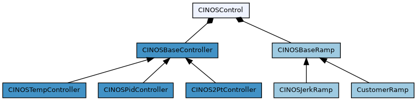
Overview of all classes which are involved in controller handling of INOS. Clicking on a class directs to the corresponding class documentation.
As shown in the class diagram, a control instance is represented by the class CINOSControl. It has two parts :
- CINOSBaseRamp is responsible for the trajectory generation
- CINOSBaseController represents the base classof the controller itself
- CINOSPidController represents a standard PID controller
- CINOSTempController represents a PID controller optimized for temperature control
- CINOS2PtController represents a simple two point controller
General
A control instance is created dynamically via the INCO tree and is usually done with our good old stream file mechanism. Refere to the temperature controller for an example.
The values have the following meaning :
- Name The controller name
- TrajectoryType The trajectory type. Valid types are INOSJerk, INOSTrapeze or an own customer specific type
- ControllerType The controller type. Valid types are INOSPid, INOSTemp, INOS2Pt or an own customer specific type
- InputName The controller input name
- OutputName The controller output name
Example :
This call creates a control instane named 'Zone0' with a jerk ramp trajectory generator and a controller of type INOSTemp. The name of the input channel (in this case the name of the temperature process image value) is ADP_02.AI_02_00. The name of the command output (in this case a digital output) is ADP_02.DO_02_00.
To be able to use the digital output as a pseudo 'analog' output, one has the possibility tell the system to handle it as a software PWM (pulse wide modulation). This can be done like this :
Example of a pwmoutput.dt2:
The values have the following meaning :
- Name The name of the digital output
- SyncName If the PWM has to be synchronized to the 230V/110V power, one can define here the name of the digital input which provides the power sync signal
- SwitchTime The fastest switching time [us], usually this is 10000us for a 230V/50Hz environment if one is working with a solid state relais
- SwitchTime60Hz The fastest switching time [us], usually this is 8000us for a 110V/60Hz environment if one is working with a solid state relais
- SyncShift If a sync input is involved, this is the time [us] between sync and output set, 2000us is usually a good choice
- Average Smoothen the the power output over this number of cylces (0 if not used)
Setting the INOS system variable
enables an automatic power frequency detection. This feature is only useful and available if there is at least one out pwm channel defined with a configured synchronisation input.
If no 60 Hz switching time is configured (SwitchTime60Hz not defined), a default value of 8000us is used. For information purposes, the detected frequency is available in the INCO tree here :
Temperature control
The temperature controller bases on a standard PID controller with some temperature related optimizations, like
- heat capacity support to improve as fast as possible jumps to a new commanded temperature
- support for the Stefan Boltzmann law (see https://en.wikipedia.org/wiki/Stefan-Boltzmann_law)
- several feed forward possibilities
- alarm temperature support
- asymmetric integrator limitation
- temperature dependent PID parameter sets
- different PID parameter sets for 'run' and 'halt'
- ...
Properties
The properties are described in the following section. To get stared, just copy the section below to a new file, name it something like myzone.stream and put the file into the config section of your project.
Errors
A list of the possible errors on the main control level. Each error can be masked by setting the corresponding bit in ErrorMask. The error ends up in inactivating the controller if the corresponding bit in ErrorDis is set (default for all errors)
| Equal | Pattern | Description |
|---|---|---|
| ER_INOS_CTRL_REJECTED | 0x00000001 | Command was rejected |
| ER_INOS_CTRL_FAILED | 0x00000002 | Command failed |
| ER_INOS_CTRL_REMOTE | 0x0000003C | Possible remote controller errors. These bits are customer specific and are not set in 'normal' applications |
| ER_INOS_CTRL_GROUP | 0x00000800 | Group member is on error. See also 'Prop.EnbOutput'. |
| ER_INOS_CTRL_BUS | 0x00001000 | Fieldbus is on error, like 'link down', 'frame error counter', ... |
| ER_INOS_CTRL_TARGET | 0x00002000 | Target is on error, like a 'trap', 'overtemperature', ... |
| ER_INOS_CTRL_CONTROL | 0x00004000 | Temperature controller is os on error. See Control.Error for a detailed error description |
| ER_INOS_CTRL_RAMP | 0x00008000 | Trajectory generator is on error. |
| ER_INOS_CTRL_SAFETY | 0x00010000 | Application specific 'safety' error (customer specific) |
| ER_INOS_CTRL_APPLICAT | 0x00020000 | General application error (customer specific) |
A list of the possible errors on the temperature controller level. Each error can be masked by setting the corresponding bit in Control.ErrorMask. The error ends up in inactivating the controller if the corresponding bit in Control.ErrorDis is set (default for all errors).
| Equal | Pattern | Description |
|---|---|---|
| ER_INOS_CONTROLLER_VALCHK | 0x00000001 | Controller value check error |
| ER_INOS_CONTROLLER_SETTLE | 0x00000002 | Settling timeout |
| ER_INOS_CONTROLLER_OUTCHN | 0x00000800 | Output channel not found |
| ER_INOS_CONTROLLER_INPCHN | 0x00001000 | Input channel not found. |
| ER_INOS_CONTROLLER_ACTIVATE | 0x00002000 | Controller activation failed for some reason |
| ER_INOS_CONTROLLER_EXTERN | 0x00004000 | External controller on error (customer specific) |
| ER_INOS_CONTROLLER_OFFLINE | 0x00008000 | Value channel is offline |
| ER_INOS_TEMP_CONTROLLER_BREAK | 0x00010000 | Set if controller's input channel reports a broken sensor (i.e. DF_INOS_IMAGE_VALUE_CFG_ERROR flag set) or if reported value exceeds the configured m_rTbreak temperature |
| ER_INOS_TEMP_CONTROLLER_SHORT_CIRCUIT | 0x00020000 | Set if controller's input channel reports a sensor short circuit |
| ER_INOS_TEMP_CONTROLLER_ALARM | 0x00040000 | Set if the temperature exceeds the configured 'alarm temperature' |
| ER_INOS_TEMP_CONTROLLER_OUT_FAILURE | 0x00080000 | Set if the temperature change does not happen as expected, although the controller puts energy into the system. IOW: The system assumes that the spent energy is not properly translated into the desired temperature change due to an error in the electrical part of the output circuit |
| ER_INOS_TEMP_CONTROLLER_DELTA | 0x00100000 | Set if the temperature delta is bigger than the maximum "speed" (i.e. maximum expected/possible temperature change within a given time span) of the temperature controller. This error indicates a problem with the sensors/actors as the temperature should is physically not expected to change that much |
| ER_INOS_TEMP_CONTROLLER_OUTPWM_SYNC | 0x00200000 | Set if the outpwm sync input does not toggle |
| ER_INOS_TEMP_CONTROLLER_LIMIT | 0x00400000 | Set if an external temperature supervision reports a limit reached error |
Warnings
A list of the possible warnings on the main control level. Each warning can masked by setting the corresponding bit in WarningMask
| Equal | Pattern | Description |
|---|---|---|
| WR_INOS_CTRL_IGNORED | 0x00000001 | Command was ignored for some reason |
| WR_INOS_CTRL_CONTROL | 0x00004000 | Temperature controller has a pending warning. See Control.Warning for a detailed error description |
| WR_INOS_CTRL_RAMP | 0x00008000 | Trajectory generator has a pending warning. |
A list of the possible warnings on the temperature controller level. Each warning can be masked by setting the corresponding bit in Control.WarningMask
| Equal | Pattern | Description |
|---|---|---|
| WR_INOS_CONTROLLER_INTLIMIT | 0x00000001 | Integrator limit reached |
| WR_INOS_CONTROLLER_NOTSUP | 0x00000002 | General 'not supported' warning |
| WR_INOS_TEMP_CONTROLLER_LOW_TEMP | 0x00010000 | Temperature too low for e.g. 'Tune=Blz' or 'Tune=ffS' |
| WR_INOS_TEMP_CONTROLLER_HIGH_TEMP | 0x00010000 | Temperature too high for e.g. 'Tune=Hcp'. In this case the temperature has to be smaller than the configured 'Ramp.Max.minS'. |
Setup step by step
This section gives a step by step intro how to setup an temperature controller.
Create the configuration
A temperature controller has a analog input which represents the temperature and either an analog or a digital output for the power stage. If the power stage is controlled over a digital output (e.g. a solid state relais), one has to configure a software pwm for this output, which allows the controller to work with values from 0..100%. See General for an example.
The controller itself is set up with a so called stream file. It is an ASCII file which simply has CallProcedure and PutVariable entries and is executed at booting of the system. An example can be found here Properties.
In short :
- create a *.dt2 file with the pwm configuration (see also General) and put it into the config directory of your project
- create a *.stream file with this content Properties. To get a good starting point, adjust the following values :
Verify the configuration
After builing and loading the project to your target, let's verify if everything was setup ok. Open the INCO explorer and check if there is a folder
where 'Zone0' is the name of your controller. If you don't see this folder :
- check if the feature 'General options.Temperature control' in your iDev project is selected
- check with the eventlogger if there are some error traces regarding your controller
Now lets check if the temperature changes if we output power for a short time :
- open a Varlog and select your input and output channels to be logged (set the trigger to the output channel != 0.0). You find these channels under Image.Analog.Input/Output and/or Image.Digital.Output
- start logger
- write e.g. 10% to the output channel, wait some seconds and write 0.0 again
If you see a significant temperature change in your log, everything seems to be fine. If not, try agin with more power or check your config and wiring.
Measure heat capacity
To give the controller a hint regarding the relation between power and temperature delta, you have the possibility to measure the so called hcpFactor (heat capacity factor). This measurement makes only sense if yor heater is some kind of heating plate or similar. It definitely makes no sense for a heater like a hot air gun. Skip this section in this case.
The measurement is done by setting a predefined power for a selected time and measuring the temperature delta.
Measure the hcpFactor :
- ensure the temperature of your heater lies below Ramp.Max.minS. If this is not the case, cool down the system somehow
- set the requested pulse values.
- activate the controller. The Control.Entity.Zone0.State should now show 'ready' :
- start measurement and (read the next step before you start) :
- during the measurement the controller state Control.Entity.Zone0.State shows 'tuning'. As soon as the state goes back to 'ready', the mesdurement is done and we suggest to immediately inactivate the controller again, to avoid any overheatings
- the measure result can be found here :
- move the measure value to the properties section and don't forget to update your controller stream file as well
- a good starting point for the PID factors can be found in Result.Pid
PID factors
To setup PID factors, there is currently no reliable mechanism available. You have to do it by hand, but usually this is not really tricky.
- to avoid any errors during this work, tell the controller to disable value checking and settling supervision :
- we start PID adjustment in the predefined low range (#{ZONE0}.Ramp.Max.minS till #{ZONE0}.Control.Pid.Run.Medium, so clear Ki and Kd in this range (Halt and Run) and set Kp to a starting value e.g. 1
- activate the controller and move to a reasonable temperature of the low range (e.g. 10°C below #{ZONE0}.Control.Pid.Run.Medium)
- now 'play' around with Control.Entity.Zone0.Control.Pid.Halt.Low.Kp (typically by increasing Kp) till you get a clean temperature oscillation, use varlog to measure/view the oscillation
- after successfu oscillation measurement, set the PID values in the following manner
- you should now have a stable controller for the low range, do the same steps for medium and high range or directly use the low parameters for the other ranges, they usually fit not to bad
Optimizations
There are several possibilities to optimize and therefore 'help' the controller to do its work.
- heat capacity measurement (seen already here Measure heat capacity)
- temperature dependant power feed forward
- Boltzmann law feed forward for heating plates
To reduce the dependancy of the integrator limits
you have two possibilities to work with a power feed forward.
1. Power feed forward with ffS
The ffS mechanism is configured with the two parameters (per temperature range) :
The feed forwarded power is calculated like this
You can either let the system measure this feed forward with
or live change the parameters during active control till the current controller integrator tends to be zero
2. Power feed forward with Boltzmann law
The Stefan–Boltzmann law describes the power radiated from a black body in terms of its temperature (see https://en.wikipedia.org/wiki/Stefan-Boltzmann_law) So if your heater is e.g. similar to a heating plate, this feed forward mechanism is probably the right choice.
How to setup :
- activate the controller and move to max. / or near the max. allowed temperature
- check the controller output at this point
In this example, we measured about 14%. Setup the following parameters to get things running
The parameters have the following meaning :
- EnbBoltzmann Enable the boltzmann law
- blzTmin Minimum temperature where the law should take effect
- blzTmax Maximum temperature where the law should take effect
- blzP The requested feed forward power at blzTmax (use about 10% less value than measured)
And now happy heating !