Overview
The motion classes of INOS are responsible for all kinds of axes handling. They provide a big range of functioality beginning from simple axis moving over homing mechanisms to trajectory planning of a whole move path. Here are some customer examples based on the INOS motion library :
- optimized event based moving algorithms for pick and place machines
- planing and running 4 axes based curves in cartesian coordinates of a wire bonder
- touch down handlings based on special approaching moves reducing the speed at the target position
- dispensing free definable patterns with e.g. rounded curves based on clothoids
- running HPGL code
- ...
Example how to move with two axis :
#include <inos.h>
void SwitchOn()
{
pAxisX->
Activate(
true,
true,
true,
true);
pAxisY->
Activate(
true,
true,
true,
true);
}
void MoveXY(double adX, double adY)
{
pAxisX->
Move(adX, &SyncX);
pAxisY->
Move(adY, &SyncY);
}
StartFunction(_INI_1000_MyInit)
{
SwitchOn();
MoveXY(100, 200);
}
virtual uint32 Move(real64 arPosition, CINOSSync *apSync=DF_INOS_SYNCHRONOUS)
Move to arPosition with actual commanded jerk, acc/deceleration and velocity.
Definition inos_syn.h:289
void And(CINOSSync *aChild)
virtual uint32 Wait(uint32 aTimeout=0xFFFFFFFF) override
Provides physical aka real axis functionality.
Definition cinosphysicalaxis.h:291
virtual uint32 Activate(bool abCheckPos=true, bool abSimulatePos=false, bool abSimulateOut=false, bool abSimulateAct=false, CINOSSync *apSync=DF_INOS_SYNCHRONOUS) override
Activate axis in a given mode, e.g Activate(true,true,true,true) enables the axis in a full simulated...
#define ASSERT_ALWAYS(f)
Definition inosmacro.h:696
Example how to run a clothoid shaped square :
#include <inos.h>
#include <cinosmovepath.h>
void SwitchOn()
{
pAxisX->
Activate(
true,
true,
true,
true);
pAxisY->
Activate(
true,
true,
true,
true);
}
void SquareXY(double adX, double adY)
{
CINOSMovePath* path;
CINOSMovePath::Create(path, "Base", "Clothoid", "Constant");
path->SetAxis("X", 0);
path->SetAxis("Y", 1);
path->SetParam("Clothoid.R", 20.0);
path->SetParam("Clothoid.L", 40.0);
path->EditBegin();
path->Linear(0, adX);
path->Linear(1, adY);
path->Linear(0, -adX);
path->Linear(1, -adY);
path->EditEnd();
path->Run("Square");
CINOSMovePath::Destroy(path);
}
StartFunction(_INI_1000_MyInit)
{
CINOSBaseAxisParamSet* set = CINOSPhysicalAxis::CreateGlobalParamSet("Square");
set->SetParam("Ramp.cmdV", 400.0);
set->SetParam("Ramp.cmdA", 4000.0);
set->SetParam("Ramp.cmdB", 4000.0);
set->SetParam("Ramp.cmdJ", 40000.0);
SwitchOn();
SquareXY(100, 200);
}
Both examples are functional without controller hardware due to the fact, that the axes are activated in full simulation mode.
Axis
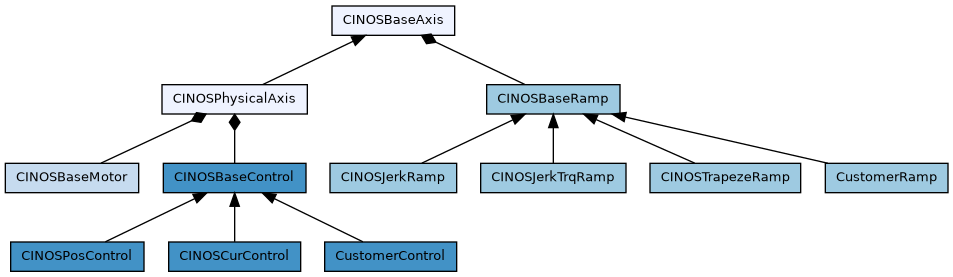
Overview of all classes which are involved in the axis handling of INOS. Clicking on a class directs to the corresponding class documentation.
As shown in the class diagram, an axis is represented by the class CINOSPhysicalAxis (the class CINOSBaseAxis is normally not used directly). It has three main parts :
- Motor represents all motor properties
- Ramp is responsible for the trajectory generation
- Control represents the axis controller
An axis is configured with a descriptor. The descriptor structure for a physical axis is defined in SINOSPhysicalAxis. The corresponding configuration file is a text file which represents the required struture. The file ending has to be 'dt2'.
Example of an axis config file x.axis.dt2:
INOS-PHYSICAL-AXIS
Name ; text_32 ; "X";
RampType ; text_32 ; "INOSJerk";
ControlType ; text_32 ; "INOSPosControl";
MotorType ; text_32 ; "INOSBaseMotor";
Options ; uint32 ; 0x00000002;
EmergencyType ; uint16 ; 1;
EmergencyDelay ; uint16 ; 10;
TestPos1 ; double ; 0.0;
TestPos2 ; double ; 100.0;
TestDelay ; uint32 ; 500;
BorderLimit ; double ; 0.2;
For a detailed explanation of every description member refere to SINOSPhysicalAxis and SINOSBaseAxis.
Motor
An motor is configured with a descriptor. The descriptor structure for a motor is defined in SINOSBaseMotor. The corresponding configuration file is a text file which represents the required struture. The file ending has to be 'dt2'.
Example of an resolver motor with 5:1 belt and 32 mm spindle config file z.motor.dt2 :
INOS-BASE-MOTOR
Name ; text_32 ; "Z";
Type ; text_32 ; "INOSBase";
Unit ; text_16 ; "mm";
TurnsPerMin ; double ; 6000.0;
IncsPerTurn ; double ; 65536;
FeedPerTurn ; double ; 32.0;
GearRatio ; double ; 5.0;
Options ; uint32 ; 0;
Digits ; uint8 ; 6;
IncPosition ; uint8 ; 0;
Example of an motor with 4096 Inc Encoder 156:25 gear in degrees config file t.motor.dt2 :
INOS-BASE-MOTOR
Name ; text_32 ; "T";
Type ; text_32 ; "INOSBase";
Unit ; text_16 ; "deg";
TurnsPerMin ; double ; 6000.0;
IncsPerTurn ; double ; 4096;
FeedPerTurn ; double ; 360.0;
GearRatio ; double ; 6.24;
Options ; uint32 ; 0;
Digits ; uint8 ; 6;
IncPosition ; uint8 ; 0;
Example of an linear motor with 20um SinCos with 4096 times interpolation and 24 mm pole pitch config file x.motor.dt2 :
100% Speed 5m/s: TurnsPerMin = 5000mm/s * 60min/s / 24mm = 12500 1/min
IncsPerTurn: 24mm/0.02mm*4096 = 4915200
INOS-BASE-MOTOR
Name ; text_32 ; "X";
Type ; text_32 ; "INOSBase";
Unit ; text_16 ; "mm";
TurnsPerMin ; double ; 12500.0;
IncsPerTurn ; double ; 4915200;
FeedPerTurn ; double ; 24.0;
GearRatio ; double ; 1.0;
Options ; uint32 ; 0;
Digits ; uint8 ; 6;
IncPosition ; uint8 ; 0;
For a detailed explanation of every description member refere to SINOSBaseMotor.
Ramp
A trajectory generator (aka Ramp) is configured with a descriptor. The descriptor structure for a ramp is defined in the corresponding structure, e.g. SINOSJerkRamp for the main stream generator. The corresponding configuration file is a text file which represents the required structure. The file ending has to be 'dt2'.
Example of a jerk ramp config file x.jerkramp.dt2:
INOS-JERK-RAMP
Name ; text_32 ; "X";
Unit ; text_16 ; "mm";
Scmd ; double ; 0.0;
Vcmd ; double ; 1000.0;
Acmd ; double ; 10000.0;
Bcmd ; double ; 10000.0;
Jcmd ; double ; 1000000.0;
Bemg ; double ; 10000.0;
Smin ; double ; 0.0;
Smax ; double ; 0.0;
Vmax ; double ; 1000.0;
VmaxSetup ; double ; 150.0;
Amax ; double ; 10000.0;
Bmax ; double ; 10000.0;
Jmax ; double ; 4000000.0;
Options ; uint32 ; 1;
Digits ; uint8 ; 6;
CacheSize ; uint8 ; 32;
For a detailed explanation of every description member refere to SINOSBaseRamp and SINOSJerkRamp.
Control
An axis controller is configured with a descriptor. The descriptor structure for a controller is defined in the corresponding structure, e.g. SINOSPosControl for the default Indel target controller. The corresponding configuration file is a text file which represents the required structure. The file ending has to be 'dt2'.
Example of a position control config file x.posctrl.dt2:
INOS-POS-CONTROL
Name ; text_32 ; "X";
PosName ; text_32 ; "X";
Unit ; text_16 ; "mm";
DeadTime ; double ; 0.125;
Smax ; double ; 0.6;
Options ; uint32 ; 5;
Digits ; uint8 ; 6;
For a detailed explanation of every description member refere to SINOSBaseControl and SINOSPosControl.
Movepath
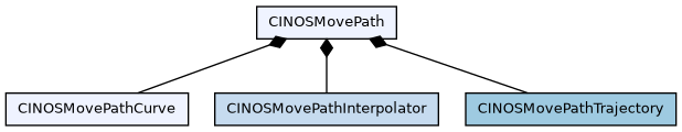
Overview of all classes which are involved in the movepath handling of INOS. Clicking on a class directs to the corresponding class documentation.
A movepath is used whenever multiple axes need to be moved on a coordinated path. Here are some examples implemented with a movepath :
- one has to move with an XY gantry from point A via point B to point C, a simple approach would be to move first to point B and in a second move to point C. Doing so would loose time. A better way is to use a movepath, where one can connect two linear moves together and blend them with an appropriate interpolator, which ensures, that the axes do not move exactly through point B and therefore do not have to stop at that point.
- a four axes handling system needs to move on a predefined path from a pick to a place position, again the simple approach would be to use single moves, the better one is to use a movepath and connect the segments together with an appropriate interpolator
- dispensing free definable patterns with e.g. rounded curves based on clothoids
As shown in the class diagram, a movepath has three main parts
- Curve represents the geometric curve definition
- Interpolator is responsible to blend movepath segments
- Trajectory is responsible for the overall trajectory generation
These three main parts need to be provided at a movepath creation. Example :
CINOSMovePath* path;
CINOSMovePath::Create(path, "Base", "Clothoid", "Constant");
The above code creates a movepath with curve type "Base", interpolator type "Clothoid" and trajectory type "Constant". Additionaly one has to map global axis names to movepath axes indexes. This can be done either globally with the static method CINOSMovePath::glbSetAxis or separate for each movepath itself with the path method CINOSMovePath::SetAxis. Example
path->SetAxis("X1", 0);
path->SetAxis("Y1", 1);
path->SetAxis("Z1", 2);
path->SetAxis("C1", 3, DF_INOS_MOVEPATH_FLAG_NLG, "SpeedAxis");
The maximum number of axes a movepath can handle is defined here DF_INOS_MOVEPATH_MAX_AXES. It can be overwritten by setting an own value in one's project inosuser.h file. Example how to increase to 5 axes :
#define DF_INOS_MOVEPATH_MAX_AXES 5
#define DF_INOS_MOVEPATH_ALL_AXES_INVOLVED 0x0000001F
The define ::DF_INOS_MOVEPATH_ALL_AXES_INVOLVED has to be equal to 2^DF_INOS_MOVEPATH_MAX_AXES-1.
Hint: To be sure, that the your number of axis is taken, you have to ensure
that the application/inosuser.h file is taken before the inosdefault.h of the operating
system. For this check in iDev Properties.C/C++ General.Path and Symbols.Includes.GNU C++
that your application/inc directory is listed before inos/os/inos/inc.
Before one is able to define the movepath geometry, one has to enter into edit mode
path->EditBegin(DF_INOS_MOVEPATH_FLAG_INC);
In the example we entered into edit mode and told the system, that all distances will be relative (incremental).
The geometry can then be defined by adding the required segments
path->SegBegin();
path->Linear(0, 100.0);
path->Linear(1, 50.0);
path->SegEnd();
path->SegBegin();
path->Linear(0, 150.0);
path->Linear(1, 250.0);
path->SegEnd();
Assume a starting point of X1=20, Y1=30. The upper example then moves first to the absolute position 120/80 and then to 270/330.
When you've done defining the path, exit the edit mode and run the path
path->EditEnd();
path->Run();
After the run, do not forget to destroy the path, otherwise you would end up with memory leaks
CINOSMovePath::Destroy(path);
For a full movepath example, see also Overview
Parts
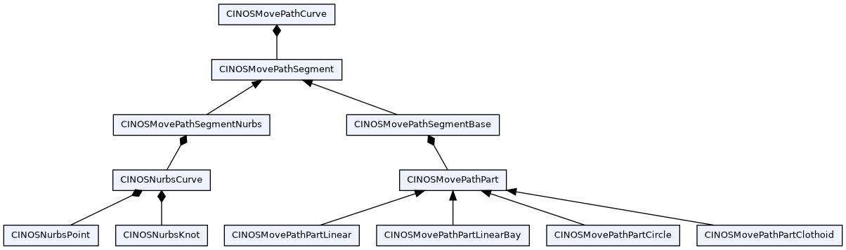
Curve
The geometry of the path to move is represented by the class CINOSMovePathCurve. A curve contains segments. Depending on the curve type, one segment has either multiple parts or one nurbs curve with an unlimited number of control points and knots. In standard use cases one does not have to care about all these classes. The following curve types are currently available :
- "Base"
- "Nurbs", The NURBS Book, Les Piegl and Wayne Tiller, ISBN 3-540-61545-8
Interpolator
The interpolator is responsible for the connection of curve segments. The following types are currently available :
- "None" no connection segments are used, this normally ends up in a stop at segment boundaries
- "Polynom" allows to smoothly (two times continous) connect segments of any kind (e.g. linear and circular segments).
- "Blend" implements the Lloyd and Hayward’s Blending algorithm (limitted to connect linear segments)
- "Shape" uses standard axis speedsets to blend between segments, blending is done by stopping e.g. one axis while an other one is already started (limitted to connect linear segments)
- "Clothoid" uses clothoids to blend two linear segments, only available for paths with two axes (e.g. X and Y)
- "Nurbs" uses nurbs to connect the segments
This list can be extended with customer interpolators. To implement a customer interpolator class, inherit the CINOSMovePathInterpolator class.
class CustomerInterpolator : public CINOSMovePathInterpolator
We recommend using the override keyword when overriding functions from the CINOSMovePathInterpolator class.
Interpolators have to be registered with their unique name and their constructor in a static map of the CINOSMovePathInterpolator class. Use the INOS_REGISTER_MOVEPATH_INTERPOLATOR macro with the interpolator name and class name as arguments to register a new interpolator. For a CustomerInterpolator class with Customer as interpolator name it is:
INOS_REGISTER_MOVEPATH_INTERPOLATOR("Customer", CustomerInterpolator);
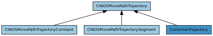
Trajectory
The trajectory class is responsible for the overall trajectory generation. It is resonsible to e.g. stop or at least reduce the speed at a segment boundary if it is necessary. The following types are currently available :
- "Constant" the whole movepath is done with a constant speed
- "Segment" reduces the requested speed if necessary on e.g. segment boundaries
Parameter
To be able to parametrise a movepath and all its involved class instances, the path provides generic SetParam and GetParm methods. We differ between general and axis specific parameters. Example :
uint32 uError = 0;
uint8 uIndexX = 0;
uint8 uIndexY = 1;
path->SetAxis("X", uIndexX);
path->SetAxis("Y", uIndexY);
path->SetParam(uIndexX, "Amax", 10000.0);
path->SetParam(uIndexX, "Bmax", 10000.0);
path->SetParam(uIndexX, "Vmax", 1000.0);
path->SetParam(uIndexX, "Jmax", 100000.0);
uError = path->SetParam("Clothoid.R", 10.0);
double dValue = 0.0;
uError = path->GetParam("Clothoid.R", dValue);
General Parameter
Here is a list of all currently available general parameters (see also cinosmovepath.h) :
Helper task
"Helper.Priority"
Setup the priority the movepath helper task should run with.
15 : highest priority
31 : lowest priority
This parameter has to be set during creation of the path, e.g. :
local path = MovePath.Create{ Curve = "Base", Interpolator = "Blend", Trajectory = "Segment", Param = "{\"Helper.Priority\":31, \"Helper.Core\":1}"}
"Helper.Core"
Setup the core the movepath helper task should run on.
0 : core 0 (default)
1 : core 1
2 : core 2
3 : core 3
This parameter has to be set during creation of the path, e.g. :
local path = MovePath.Create{ Curve = "Base", Interpolator = "Blend", Trajectory = "Segment", Param = "{\"Helper.Priority\":31, \"Helper.Core\":1}"}
General McRobot
"McRobot.PreparePath"
Define what the PreparePath method should do if an error occurs
0 : only return error code (default)
1 : set module to error and emit a corresponding message
Shape interpolator
"Shape.OnShrink"
Define what the shape interpolator should do if a transition segment needs to be shrinked
0 : reduce path velocity to not exceed Amax of any axis
1 : stop at segment boundary (default)
2 : emit an error
3 : reduce path velocity to not exceed Jmax of any axis
Nurbs interpolator
"Nurbs.MaxAngle"
Defines the max. allowed angle between two consecutive linear segments that is handled without an explicit stop
0.0 : disabled
20.0 : default
"Nurbs.MaxLength"
Linear segments that are longer than the given length are always handled separately. This allows the segment trajectory generator to speedup the path velocity accordingly during this part of the path.
0.0 : disabled
"Nurbs.Vectorize"
Non linear segments are vectorized, before given to nurbs interpolator. The given tolerance * this factor is the max allowed error, between real curve and the vector
0.1 : default
Clothoid interpolator
"Clothoid.Pure"
Defines whether the clothoid interpolator should work with pure clothoids (german 'Scheitelklothoiden') or not
0.0 : disabled
1.0 : enabled (default)
"Clothoid.Reduce"
Defines whether the clothoid interpolator should automatically reduce clothoid parameters r,l,a to fit the clothoids into the given linear segments
0.0 : disabled
1.0 : enabled (default)
"Clothoid.R"
Defines the requested clothoid radius
"Clothoid.L"
Defines the requested clothoid length
"Clothoid.A"
Defines the clothoid parameter A (=sqrtR*L)
Trajectory generator
"Trajectory.MainAxis"
Index of trajectory main axis (e.g. ramp geni is cloned from this axis)
0 : default
"Trajectory.Buffer.Type"
Default trajectory buffer type
Possible types are :
'none' : the trajectory generator pulls the data direct to the axes
'active' : the trajectory generator writes the data to an intermediate
buffer and a synchronous axes hook reads the data from the
buffer and pulls them to the axes
'passive': the trajectory generator writes the data to an intermediate
buffer and user code is responsible to read if from the
buffer and pulls it to the axes
"Trajectory.Buffer.Size"
Trajectory buffer size in entries, e.g. 256 entries for axis running with 4kHz ends up in a look ahead of 64ms
256 : default
"Trajectory.Buffer.Ready"
Trajectory buffer ready level, the path starts, when at least this number of entries are calculated
16 : default
"Trajectory.Buffer.Low"
Trajectory buffer low level, the trajectory generator calculates new entries, when the current number of entries goes below this value
192 : default
"Trajectory.Filter.Length"
Trajectory filter length, can be used to smooth the trajectory
0 : default
"Trajectory.Follow.Enable"
Trajectory axis follow mechanism. If enabled a trajectory for axis 'INDEX' is generated, that follows the tangent of axis with index 0 and 1 (e.g. if running a circle with X and Y, the T axis can follow the circle to e.g. command a cutting knife)
0 : disabled (default)
1 : enabled
"Trajectory.Follow.Index"
Index of axis which needs to follow
0 : default
"Trajectory.Follow.Unit"
Unit of following axis
0 : degrees (default)
1 : radiant
"Trajectory.Constant.CheckVelocity"
Constant trajectory, check velocity before run
Possible values are
0 : no check at all (default)
1 : check and return with error if the requested velocity is to big
2 : check and automatically reduce velocity to the max. possible one
Axis specific parameter
Axis specific parameters are handled with SetParam(index, ...) and GetParm(index, ...). Here is a list of all currently available axis specific parameters :
"Amax" Max. allowed acceleration of this axis during the path run. If not provided Amax of the axis configuration is taken (xxx.ramp.dt2)
"Bmax" Max. allowed deceleration of this axis during the path run. If not provided Bmax of the axis configuration is taken (xxx.ramp.dt2)
"Vmax" Max. allowed velocity of this axis during the path run. If not provided Vmax of the axis configuration is taken (xxx.ramp.dt2)
"Jmax" Max. allowed jerk of this axis during the path run. If not provided Jmax of the axis configuration is taken (xxx.ramp.dt2)
Error handling
Every movepath method returns either 0 if it was successful or a corresponding error code. There are two possibilities to handle errors.
The first classic one is to check for an error after every call and react accordingly if the call was not successful. This can be pretty annoying if one creates a big movepath with a lot of segments.
The second one is to work with C++ exception handling. For this, one needs to do the following :
- Activate the following iDev features :
- General options.C++ exception support
- MovePath.Exception support
- Set the additional compiler flag '-fexceptions' for the corresponding file
- right mouse click on the file -> Properties
- C/C++ Build.Settings
- Miscellaneous -> Other flags -> -fexceptions
- Use the additional option ::DF_INOS_MOVEPATH_OPTION_EXCEPTION_SUPPORT during creation of the path
Then one can write code like this :
CINOSMovePath* path = 0;
try {
CINOSMovePath::Create(path, "Base", "Shape", "Segment",
DF_INOS_MOVEPATH_OPTION_EXCEPTION_SUPPORT);
path->SetAxis("X", 0);
path->SetAxis("Y", 1);
path->EditBegin();
path->SegBegin();
path->Linear(0, 200);
path->SegEnd();
path->SegBegin();
path->Linear(1, 100);
path->SegEnd();
path->SegBegin();
path->Linear(0, -200);
path->SegEnd();
path->SegBegin();
path->Linear(1, -100);
path->SegEnd();
path->EditEnd();
path->Run("Shape");
CINOSMovePath::Destroy(path);
}
catch (CINOSException& e) {
INOS_ERROR("Movepath exception occured: Code = 0x%08lX (%s)", e.GetCode(), SINOSError::GetText(e.GetCode()));
if (0 != path) {
CINOSMovePath::Destroy(path);
}
}
Tracing
To get extended information in case of movepath errors, there are two trace levels one can activate. The level 'MovePathCreate' for all creation stuff and the level 'MovePathRun' for movement issues. Activating both in Indel Eventlogger shows the following trace for the upper example :
2017-02-10 13:29:10.346750756ns [T: Machine_Portal]
MOVEPATH[1] : Create ( 1, Base, Shape, Segment, 0x00000003 ) [0x02424CC0]
2017-02-10 13:29:10.346840196ns [T: MovePathHelper0]
MOVEPATH[1] : EditBegin ( 0x00000002, -1.000000, -1.000000 )
2017-02-10 13:29:10.346866376ns [T: MovePathHelper0]
MOVEPATH[1] : SegBegin ( 0xFFFFFFFF, 0x00000000, -1.000000, -1.000000 )
2017-02-10 13:29:10.346893076ns [T: MovePathHelper0]
MOVEPATH[1] : Linear ( 0x00, 200.000000, 0x00000000 )
2017-02-10 13:29:10.346913196ns [T: MovePathHelper0]
MOVEPATH[1] : SegEnd ( )
2017-02-10 13:29:10.346963316ns [T: MovePathHelper0]
MOVEPATH[1] : SegBegin ( 0xFFFFFFFF, 0x00000000, -1.000000, -1.000000 )
2017-02-10 13:29:10.346988136ns [T: MovePathHelper0]
MOVEPATH[1] : Linear ( 0x01, 100.000000, 0x00000000 )
2017-02-10 13:29:10.347006056ns [T: MovePathHelper0]
MOVEPATH[1] : SegEnd ( )
2017-02-10 13:29:10.347026716ns [T: MovePathHelper0]
MOVEPATH[1] : SegBegin ( 0xFFFFFFFF, 0x00000000, -1.000000, -1.000000 )
2017-02-10 13:29:10.347051276ns [T: MovePathHelper0]
MOVEPATH[1] : Linear ( 0x00, -200.000000, 0x00000000 )
2017-02-10 13:29:10.347069116ns [T: MovePathHelper0]
MOVEPATH[1] : SegEnd ( )
2017-02-10 13:29:10.347094016ns [T: MovePathHelper0]
MOVEPATH[1] : SegBegin ( 0xFFFFFFFF, 0x00000000, -1.000000, -1.000000 )
2017-02-10 13:29:10.347118796ns [T: MovePathHelper0]
MOVEPATH[1] : Linear ( 0x01, -100.000000, 0x00000000 )
2017-02-10 13:29:10.347136536ns [T: MovePathHelper0]
MOVEPATH[1] : SegEnd ( )
2017-02-10 13:29:10.347150076ns [T: MovePathHelper0]
MOVEPATH[1] : EditEnd ( )
2017-02-10 13:29:10.347184816ns [T: MovePathHelper0]
MOVEPATH[1] : Run ( Shape )
2017-02-10 13:29:10.347192136ns [T: MovePathHelper0]
MOVEPATH[1] : Pos [ 0.000000, 0.000000, 0.000000, 0.000000 ]
2017-02-10 13:29:11.357950636ns [T: MovePathHelper0]
MOVEPATH[1] : Done ( 0x00000000 )
2017-02-10 13:29:11.357957696ns [T: MovePathHelper0]
MOVEPATH[1] : Pos [ 0.000000, 0.000000, 0.000000, 0.000000 ]
2017-02-10 13:29:11.357986556ns [T: Machine_Portal]
MOVEPATH[1] : Destroy (1) [0x02424CC0]
#define MOVEPATH
Definition inosdefine.h:640
Lua binding
You can create a movepath not only from C++ but also within a Lua script. To make the MovePath Lua module available, enable feature MovePath > Lua binding in the iDev feature settings of your project.
Example (linear segments connected with a shape interpolator, set priority of helper task to 31 and let it run on core 1) :
local MovePath = require "MovePath"
local path = MovePath.Create{ Curve = "Base", Interpolator = "Shape", Trajectory = "Segment", Param = "{\"Helper.Priority\":31, \"Helper.Core\":1}"}
path:SetAxis("X", 0)
path:SetAxis("Y", 1)
path:EditBegin{ Flags = "Absolute", Tolerance = Tolerance}
path:SegBegin()
path:Linear(0, 100)
path:Linear(1, 200)
path:SegEnd( )
path:SegBegin()
path:Linear(0, 10)
path:Linear(1, 20)
path:SegEnd( )
path:EditEnd ()
Mc.Module.Portal.Cmd.RunPath(path, "Shape")
Example (Nurbs curve) :
local MovePath = require "MovePath"
local path = MovePath.Create{ Curve = "Nurbs", Interpolator = "None", Trajectory = "Segment"}
path:SetAxis("X", 0)
path:SetAxis("Y", 1)
path:EditBegin()
path:NrbBegin()
path:NrbPoint(0.0, 0.0);
path:NrbPoint(30.0, 0.0);
path:NrbPoint(60.0, 30.0);
path:NrbPoint(90.0, 30.0);
path:NrbEnd()
path:EditEnd()
Mc.Module.Portal.Cmd.RunPath(path, "Shape")
Example (Circle as a Nurbs curve):
- See also
- http://geometrie.foretnik.net/files/NURBS-en.swf
local MovePath = require "MovePath"
local path = MovePath.Create{ Curve = "Nurbs", Interpolator = "None", Trajectory = "Segment"}
path:SetAxis("X", 0)
path:SetAxis("Y", 1)
path:EditBegin()
-- to start point
path:NrbBegin();
path:NrbPoint(0.0, 0.0, 1.0);
path:NrbPoint(50.0, 0.0, 1.0);
path:NrbEnd();
-- the circle
path:NrbBegin{ Degree = 2};
path:NrbPoint(50.0, 0.0, 1.0);
path:NrbPoint(100.0, 0.0, 0.707);
path:NrbPoint(100.0, 50.0, 1.0);
path:NrbPoint(100.0, 100.0, 0.707);
path:NrbPoint(50.0, 100.0, 1.0);
path:NrbPoint(0.0, 100.0, 0.707);
path:NrbPoint(0.0, 50.0, 1.0);
path:NrbPoint(0.0, 0.0, 0.707);
path:NrbPoint(50.0, 0.0, 1.0);
path:NrbKnot(0.0, 3);
path:NrbKnot(0.25, 2);
path:NrbKnot(0.50, 2);
path:NrbKnot(0.75, 2);
path:NrbKnot(1.0, 3);
path:NrbEnd();
path:EditEnd ()
Mc.Module.Portal.Cmd.RunPath(path, "Shape")
Example (Calculating length and velocity of MovePath):
local MovePath = require "MovePath"
local path = MovePath.Create{ Curve = "Base", Interpolator = "Shape", Trajectory = "Segment", Param = "{\"Helper.Priority\":31, \"Helper.Core\":1}"}
path:SetAxis("X", 0)
path:SetAxis("Y", 1)
path:EditBegin{ Flags = "Absolute", Tolerance = Tolerance}
path:SegBegin()
path:Linear(0, 100)
path:Linear(1, 200)
path:SegEnd( )
path:SegBegin()
path:Linear(0, 10)
path:Linear(1, 20)
path:SegEnd( )
path:EditEnd ()
-- PreparePath needs to be run before using methods such as GetMoveLength
path = Mc.Module.Portal.Cmd.PreparePath(path, "Shape"):GetResults()
print("lenght: " .. path:GetMoveLength())
print("velocity: " .. path:GetMaxConstantVelocity())
Mc.Module.Portal.Cmd.RunPath(path, "Shape")
To run the path, you have to hand it over to the corresponding McRobot module which is responsible for the selected axes. Note that the RunPath command used for that is a different overload than the one visible in the INCO tree: The one called from Lua is CINOSMcRobot::eCmdRunPath and takes arguments (CINOSMovePath Path, string SpeedSet). The one in the INCO tree is CINOSMcRobot::eCmdRunPathStr and takes arguments (string PathName, string SpeedSet, string Param) (where Param is currently ignored).
You do not have to destroy the path yourself after the run, the system is doing that for you.
There is more or less a one to one relation between C++ methods and Lua functions. To work with movepath functionality, you need to import the 'MovePath' module :
local MovePath = require "MovePath"
In Lua we differ between library and path functions. You can use direct or named parameters. We suggest to use named parameters. The used abbreviations have the following meaning :
- nnn a number is required
- sss a string is required
- Flags the strings "Absolute", "Incremental" and "NotLengthRelevant" are allowed
The following library functions are available in Lua :
Click on the method to get directed to the corresponding description.
MovePath.Create
local path = MovePath.Create { Options = nnn }
local path = MovePath.Create { Name = sss, Options = nnn }
local path = MovePath.Create { Curve = sss, Interpolator = sss, Trajectory = sss, Options = nnn }
local path = MovePath.Create { Name = sss, Curve = sss, Interpolator = sss, Trajectory = sss, Options = nnn }
MovePath.SetAxis
MovePath.SetAxis{ Name = sss, Index = nnn, Flags = sss, Options = nnn }
MovePath.GetActPosition
local pos = MovePath.GetActPosition{ Name = sss }
The following path methods are available in Lua :
Click on the method to get directed to the corresponding description.
SetAxis
path:SetAxis{ Name = sss, Index = nnn, Flags = sss, Type = sss }
EditBegin
path:EditBegin{ Flags = sss, Tolerance = nnn, Velocity = nnn }
EditEnd
SegBegin
path:SegBegin{ Id = nnn, Flags = sss, Tolerance = nnn, Velocity = nnn }
SegEnd
NrbBegin
path:NrbBegin{ Id = nnn, Flags = sss, Degree = nnn, InterpolationPoints = nnn, Velocity = nnn }
NrbEnd
NrbPoint
path:NrbPoint{ P0 = nnn, P1 = nnn, ... , Weight = nnn }
NrbKnot
path:NrbKnot{ Value = nnn, Multiplicity = nnn }
Start
path:Start{ Index = nnn, Position = nnn }
Linear
path:Linear{ Index = nnn, Position = nnn, Flags = sss }
LinearBay
path:LinearBay{ Index1 = nnn, Index2 = nnn, Position1 = nnn, Position2 = nnn, Length = nnn, Flags = sss }
CircleCW
path:CircleCW { Index1 = nnn, Index2 = nnn, End1 = nnn, End2 = nnn, Mid1 = nnn, Mid2 = nnn, Flags = sss }
CircleCC
path:CircleCC { Index1 = nnn, Index2 = nnn, End1 = nnn, End2 = nnn, Mid1 = nnn, Mid2 = nnn, Flags = sss }
CircleCW_Angle
path:CircleCW_Angle { Index1 = nnn, Index2 = nnn, Mid1 = nnn, Mid2 = nnn, Angle = nnn, AngleAbsolute = nnn, Flags = sss }
CircleCC_Angle
path:CircleCC_Angle { Index1 = nnn, Index2 = nnn, Mid1 = nnn, Mid2 = nnn, Angle = nnn, AngleAbsolute = nnn, Flags = sss }
CircleCW_Radius
path:CircleCW_Radius { Index1 = nnn, Index2 = nnn, End1 = nnn, End = nnn, Radius = nnn, Flags = sss }
CircleCC_Radius
path:CircleCC_Radius { Index1 = nnn, Index2 = nnn, End1 = nnn, End = nnn, Radius = nnn, Flags = sss }
SetParam
path:SetParam { Name = sss, Value = nnn }
path:SetParam { Name = sss, Value = sss }
path:SetParam { Index = nnn, Name = sss, Value = nnn }
path:SetParam { Index = nnn, Name = sss, Value = sss }
GetParam
local value = path:GetParam { Name = sss, Default = nnn }
local value = path:GetParam { Name = sss, Default = sss }
local value = path:GetParam { Index = nnn, Name = sss, Default = nnn }
local value = path:GetParam { Index = nnn, Name = sss, Default = sss }
GetMoveTime
local time = path:GetMoveTime ( )
GetMoveTicks
local ticks = path:GetMoveTicks ( )
GetMoveLength
local length = path:GetMoveLength ( )
GetPositionDelta
local pos1,pos2,... = path:GetPositionDelta ( )
GetMaxConstantVelocity
local length = path:GetMaxConstantVelocity ( )